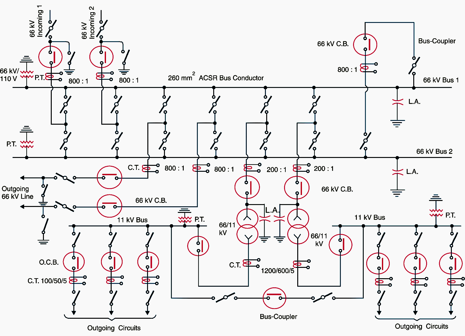

There are often complicating factors that will interact with and govern certain aspects of design functionality, converting a straight-forward design process into a more iterative approach (think “Newton-Raphson method”). It’s not always true that one-line and schematic design will come first in the design process. Once the aspects of functionality are worked out, other details can then start being fitted into place. The single-lines will show the big picture, while the schematic will show the functional picture. Schematic diagrams show the network of contacts, a network that can be extremely complex, and the relays and motors that those contacts actuate.Ĭreating draft versions of single-line and schematic diagrams is part of the process of working out the final design aspects. For example, 120-volt relay logic is still in widespread use in nuclear plants. The schematic diagram is a symbolic presentation of a system’s control elements that makes it easier to understand an electrical system’s functional logic. Schematics typically show devices like the electrical power bus, breakers, fuses, electrical loads like relays and breakers, relay contacts, switches, and indicator lights. Schematic diagrams show the functionality of more mid-level electrical circuits without getting bogged down in the details of individual connections (which are shown on wiring diagrams). Single-line diagrams are where upper-level details like generators, main transformers, and large motors are shown. They typically condense three-phase connections down to single lines for simplicity.

Single-line diagrams show the overall conceptual layout of a circuit. The differences aren’t necessarily intuitive at first glance. Single-line and schematic diagrams each have their respective places in the design process.


 0 kommentar(er)
